ROI
App Chat
Free Report
Notes
Tips
FAQ
Videos
Case Studies
Microgage Alignment over Long Measuring Runs & Surfaces
Overview
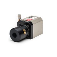
Many alignment applications with the Laser Microgage involved monitoring flatness or straightness of travel down a long path — an ideal application for this product. Significant time savings in alignment can be realized by following a simple procedure outlined in this Tech Tip. The issue we address is how to make precise measurements of surface flatness or travel by using some simple calculations to minimize the measurement set-up time and the alignment of the laser beam. The Microgage receiver views the position of the laser beam many times per second and calculates the position of the center of the laser beam relative to the machined base of the receiver and provides a digital display proportional to this distance.
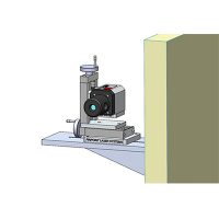
If you are aligning the laser to a long measuring run (see Figure #1,) the beam may not be parallel to the surface that you are trying to measure. Consequently, as the receiver is moved down the measuring run, the readings may gradually increase or decrease. This effect can be eliminated by carefully aligning the laser so that the readings at Point 1 and Point 2 are equal before you start — however, this can be time-consuming and frustrating if you are attempting to align a laser to within 0.001 inch or better over distances greater than 10 feet. There is an easier way. Begin by taking a Microgage reading at Point 1 and at Point 2 as shown on Figure #2, and also record the distance between the two reading locations. By knowing the difference between the two readings at the endpoints of your measuring run and the distance between them, you can calculate exact beam position anywhere along the run and apply it to your measurement.
Example
Consider the readings given in Figure #2: At the starting position you have a Microgage reading of 0.010″, and at the end of the run, 10 feet away, you see a reading of 0.070″. The difference between these two readings is 0.060 inch, occurring over a run of 10 feet. By dividing 0.060 inch by 10 feet, we find that the Microgage reading should increase by 0.006 inch for every 12 inches of travel down the measuring run. This is made possible by the fact that light travels in a straight line. Mathematically, the expression is given as follows:
Laser Beam Offset = [2nd Reading – 1st Reading] = [0.070 – 0.010]Distance Between Measurements 10′ or 120″ Thus, 0.060″ / 120 inches is 0.0005 inch per inch of travel, or every 2 inches of travel along the measuring run is equivalent to a Laser Beam Offset of 0.001 inch. Now we can apply this laser beam offset to our measurements using the following relationship:
Corrected Reading = [Laser Beam Offset X Distance] + 1st Reading
where the first reading is the one closest to the Microgage laser. Referring back to our example, at 5 feet from the first reading point, the correct measurement, if the surface being inspected is truly flat, should be 0.040 inch (i.e.: {{0.0005 x 60 inches} + 0.010 inch}. This same relationship repeats up and down the measuring run so that at 3 feet, you have 0.028 inch, at 4 feet, 0.034 inch, etc. If your readings vary from these calculated values, you know that the surface you are measuring is not flat or straight. We hope that this Tech Tip will save you time and expand your capabilities with the Laser Microgage. Please contact our Engineering Support Group at helpdesk@pinpointlaser.com if you have questions or suggestions for other applications.
Talk to our alignment specialists